Parameterization for a BiSS® C encoder
- 1. Select the subordinate device "EP7041-0000" in the Solution Explorer.
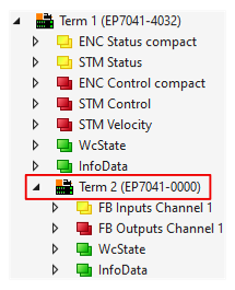
- 2. Select the value 0 "BiSS-C" in CoE parameter 8008:18 "Mode".
- The parameter 0x8008:02 "Disable Status Bits" is automatically set to FALSE.
- 3. Configure the encoder with the following CoE parameters:
- 0x8008:11 "CRC polynomial"
Enter the CRC polynomial used by the encoder to calculate the checksum here.
Common values are the default value 0x43 (67dec.) or 0x97 (151dec).
Not recommended: You can deactivate the CRC check by setting "CRC polynomial" to 0.
As a rule, the CRC checksum is transmitted inverted. If not, set the CoE parameter 0x8008:03 "CRC invert" to FALSE. - 0x8008:13 "Clock Frequency"
Set the clock frequency at which the EP7041-4032 should read the values from the encoder here. Value range: max. 10 MHz.
Select a clock frequency that does not exceed the maximum clock frequency of the encoder.
Also take into account possible restrictions due to long cable lengths. - 0x8008:15 "Multiturn [Bit]"
The multi-turn resolution of the encoder. It corresponds to the number of multi-turn bits transmitted by the encoder.
If the encoder only provides single-turn bits (e.g. linear encoder), set "Multiturn [Bit]" to "0". - 0x8008:16 "Singleturn [Bit]"
The single-turn resolution of the encoder. It corresponds to the number of single-turn bits transmitted by the encoder. - 0x8008:17 "Offset LSB Bits [Bit]"
You can use the "Offset LSB Bits" to hide additional bits that some encoders transmit after the position data in the BiSS® C frame, e.g. a parity bit or a power good bit.
Structure of a BiSS® C frame
Offset MSB Bit (optional) | Position [max. 64 bits] | Offset LSB Bit | Error [1 bit] | Warning [1 bit] | CRC [8 bit] | |
|---|---|---|---|---|---|---|
Not relevant | Multi-turn data | Single-turn data | Optional | Status bits | CRC polynomial | |
0x80p8:15 | 0x80p8:16 | 0x80p8:17 | 0x80p8:02 | 0x80p8:11 | ||
Error handling
The following status bits are available in the process data for error handling of the BiSS® C interface:
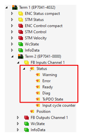
Warning | Error | Ready | TxPDO | Error description | Possible causes |
|---|---|---|---|---|---|
0 | 0 | 1 | 0 | No error, | Encoder is connected correctly, communication is established |
0 | 0 | 0 | 1 | Encoder is not ready for communication, or position value is invalid | Wiring error: Incorrect parameterization: Communication error: |
0 | 0 | 1 | 1 | Encoder is ready for communication, but position value is invalid | Incorrect parameterization: Communication error: |
1 | 0 | X | 0 | BiSS® C warning bit set | Encoder-specific warning, check manufacturer's data sheet |
0 | 1 | X | 1 | BiSS® C error bit set | Encoder-specific error, check manufacturer data sheet |
X | X | X | X | Position value is invalid | Incorrect parameterization: |
1 | 1 | X | 1 | BiSS® C warning and error bit set | Encoder-specific error and warning, check manufacturer's data sheet |
Legend
Status | Description |
|---|---|
1 | Permanent bit status TRUE |
X | Bit Change of state, depending on the encoder position |