EL8601-8411 - Devices diagnostic functions
The status of the LEDs can be read electronically via CoE object 0xF915:0. The status of the LEDs is displayed as a 32-bit value. The value is interpreted as follows.
- Byte 1 indicates the flashing/lighting code with
- 0x00: LED off
- 0x01 to 0x82: flashing codes
- 0xFF: LED on
- Byte 4 (R), byte 3 (G) to byte 2 (B) specify the color as an RGB code.
Byte 1 | Byte 2 | Byte 3 | Byte 4 | Meaning |
|---|---|---|---|---|
0x00 | 00 | 00 | 00 | LED not present |
0x00 | FF | 00 | 00 | LED is off (blue) |
0x00 | 00 | FF | 00 | LED is off (green)
|
0x00 | 00 | 00 | FF | LED is off (red)
|
0x00 | 00 | FF | FF | LED is off (yellow) |
0x00 | FF | FF | FF | LED is off (white) |
0x01 to 0x14 | 00 | FF | 00 | LED flashes at 1 Hz to 20 Hz (green) |
0x80 | 00 | FF | 00 | Run LED flashing uniformly (green): EtherCAT State Machine: PREOP |
0x81 | 00 | FF | 00 | Run LED flashing slowly (green): EtherCAT State Machine: SAFEOP |
0x82 | 00 | FF | 00 | Run LED flashing quickly (green): EtherCAT State Machine: BOOT |
0xFF | FF | 00 | 00 | LED is on (blue) |
0xFF | 00 | FF | 00 | LED on (green)
|
0xFF | 00 | 00 | FF | LED is on (red)
|
0xFF | 00 | FF | FF | LED is on (yellow) |
0xFF | FF | FF | FF | LED is on (white) |
LED status using the EL8601-8411 multi-functional terminal as an example
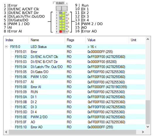 Fig.179: EL8601-8411 LED display with the corresponding CoE values in index 0xF915:0