Primary side connection (push-in wiring)
| |
Dangerous electrical voltage leads to electric shock and arc flashover! Non-compliance will result in death, personal injury or considerable material damage!
|

Plug and unplug the wire
- The wire is connected using the direct plug-in technique,
- i.e. no tools required for solid wires and ferrules, the wire is simply inserted into the contact point after stripping
- Free stranded wire ends can also be connected in this way; in this case the wire clamping mechanism has to be opened by operating the pushing device.
- Note the assignment of the individual primary conductors according to the printing on the top of the housing see following figure!
- The wires are released via the contact release device, using a screwdriver or pushing device see figure below (A).
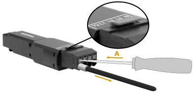 Fig.6: Connection of primary conductor to SVL1xx3 low-power transformer
Notice | |
Do not pull the conductor when live or under load The cables must not be live or plugged/unplugged under load. |
The permitted wire cross-sections and the strip length are shown in the following table.
Wire cross-section (solid wire) | 0.2 ... 4 mm2 |
Cable cross-section (stranded wire) | 0.2 ... 4 mm2 |
Cable cross-section (stranded wire) | 0.25 ... 4 mm2 (with ferrule with plastic collar) |
Cable cross-section (stranded wire) | 0.25 ... 4 mm2 (with ferrule without plastic collar) |
Conductor cross-section AWG | 24 … 10 |
Strip length | 10 ... 12 mm / 0.39 – 0.47 in |
Insert and pull the push-in service plug
The push-in plug is included.
The push-in plug is designed as a service plug. Maximum number of mating cycles: 25
For maintenance purposes, e.g. during service, the entire plug-in body can be removed from the transformer without releasing the individual wires. Proceed as follows:
- Grasp the transformer housing firmly with one hand.
- Press the locking tab with the thumb of your other hand and remove the plug from the housing.
- Insert the plug until you hear it click into place.
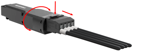 Fig.7: SVL1xxx - Remove the service plug
Notice | |
Do not insert/remove the service plug under load The service plug has no specified switching capacity and must not be plugged/unplugged live or under load. |