| FC310x - PCI Cards for PROFIBUS |
FC310x - Master Diagnostics
Diagnostic Inputs
The master possesses a variety of diagnostic variables that describe the state of the card and of the Profibus. They can be linked in the PLC:
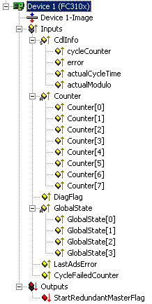
CdlInfo:
CdlInfo.error: Shows the number of slaves with which data exchange could not take place in the last cycle. The BoxState of the slaves should only be checked if this value is not equal to 0.
CdlInfo.cycleCounter: Is incremented at the end of each PROFIBUS cycle in order that this variable can indicate whether the last cycle was completed before the task was started.
CdlInfo.actualCycleTime: Shows the current cycle time in 4/25 µs. This variable is updated only when all slaves are involved in the data exchange (also when CdlInfo.error is 0).
CdlInfo.actualModulo: Indicates the current modulo. This variable is only of significance if the slaves are prioritized (see the Slave Prioritization/Multiple DP Cycles chapter)
Counter: Used for the Redundancy mode
DiagFlag: Indicates whether the card's master diagnostic information has changed. It can then be read via ADS by the control program, after that the "DiagFlag" variable is reset.
GlobalState: GlobalState[0] indicates the state of the FC310x, GlobalState[1-2] indicate global bus statuses, while GlobalState[3] is reserved for extensions:
RESET (1): Card router not started (after start-up of the PC).
INIT (2): Router started but card not active on PROFIBUS.
STOP (3): Card active on PROFIBUS, but no cyclic data exchange.
STOPPING (4): Card ends cyclic data exchange.
RUN (0): Card in cyclic data exchange.
GlobalState[1] counts the detected bus errors (as from FC310x, version 1).
GlobalState[2]: Bit 0 is set, if no 11 bit idle time is detected on the PROFIBUS (-> check cabling), bit 1 contains the operation mode CLEAR (bit 1 = 1) or OPERATE (bit 1 = 0), the other bits (2..7) are reserved for expansions (from FC310x, version 1).
GlobalState[3] is reserved for expansions.
CycleFailedCounter: This counter shows how often the FC310x PROFIBUS cycle was unready at the start of the TwinCAT task.
StartRedundantMasterFlag: Is used for the Redundancy mode
Master Diagnostics Data
The master diagnostic data can be read by ADS:
ADS-Read parameters | Meaning |
|---|---|
Net-ID | Net-ID of the master (see the device's ADS tab) |
Port | 200 |
IndexGroup | 0x0000F100 |
IndexOffset | Offset within the diagnostic data |
Length | Length of the diagnostic data that is to be read |
Data | Diagnostic data |
The master diagnostic data has the following structure:
Offset | Description |
|---|---|
0 -125 | BusStatus list, one byte per station address 0-125, which contains the station status (see BoxState for PROFIBUS boxes, additional for stations that are not configured: 0x80 - not available, 0x81 - slave, 0x82 - master not ready for token ring, 0x83 - master ready for token ring, 0x84 - master in token ring) |
126 - 127 | reserved |
128 - 135 | State of the FC310x (->GlobalState) |
136 - 137 | Send error counter for all sent telegrams |
138 - 139 | Receive error counter for all received telegrams |
140 - 255 | reserved for extensions |
256 - 257 | |
258 - 259 | Cycle Start Error Counter, counts up one when the PROFIBUS cycle is restarted before the old cycle is complete (intercepted by the TwinCAT-IO driver, only possible with customized drivers) |
260 - 261 | |
262 - 263 | reserved for extensions |
264 - 265 | Minimum reload value of real-time timer |
266 - 267 | |
268 - 269 | |
270 - 271 |
TcIo diagnostic data
The TcIo driver also generates diagnostic data that can be read, activated, deactivated and reset by ADS. It is, however, deactivated by default. They are enabled if the tab EquiDiag or GeneralDiag (TwinCAT 2.8) MC-Diag or DP-Diag of the device is selected and disabled if the tab if deselected.
Activation, deactivation and resetting the TcIo diagnostic data
ADS-Write parameters | Meaning |
|---|---|
Net-ID | PC Net-ID |
Port | 300 |
IndexGroup | 0x00005000 + Device-Id (device's General tab) |
IndexOffset | 0xFFFFF100 |
Length | 2 |
Data | 0: Deactivation of the Tclo diagnostic data 1: Activation of the Tclo diagnostic data 2: Resetting the Tclo diagnostic data |
Reading the Tclo diagnostic data
ADS-Read parameters | Meaning |
|---|---|
Net-ID | PC Net-ID |
Port | 300 |
IndexGroup | 0x00005000 + Device-Id (device's General tab) |
IndexOffset | 0xFFFFF100 |
Length | Length of the Tclo diagnostic data |
Data | TcIo diagnostic data |
The Tclo diagnostic data has the following structure:
Offset | Description |
|---|---|
0 -3 | |
4 - 7 | |
8 - 11 | |
12 - 15 | |
16 - 19 | CycleWithNoDxch counter (see tab GeneralDiag (TwinCAT 2.8) or DP-Diag (TwinCAT 2.9)) |
20 - 23 | CycleWithRepeat counter (see tab GeneralDiag (TwinCAT 2.8) or DP-Diag (TwinCAT 2.9)) |
24 - 27 | Max. repeater/cycle (see tab GeneralDiag (TwinCAT 2.8) or DP-Diag (TwinCAT 2.9)) |
28 - 31 | Actual cycle time (in 4/25 µs, see tab GeneralDiag (TwinCAT 2.8) or DP-Diag (TwinCAT 2.9)) |
32 - 35 | Max. cycle time (in 4/25 µs, see tab GeneralDiag (TwinCAT 2.8) or DP-Diag (TwinCAT 2.9)) |
36 - 39 | Max. cycle time (in 4/25 µs, see tab GeneralDiag (TwinCAT 2.8) or DP-Diag (TwinCAT 2.9)) |
40 - 43 | RealFailedCycle counter (see tab GeneralDiag (TwinCAT 2.8) or DP-Diag (TwinCAT 2.9)) |
44 - 47 | |
48 - 51 | |
52 - 55 | |
56 - 59 | |
60 - 63 | |
64 - 67 |