MC_AxRtReadPressureDiff_BkPlcMc
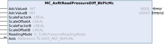
 | Available from version 3.0 |
The function block handles determination of the actual pressure of the axis from the input data of two analog input terminals.
| If only one input signal is available, a function block of type MC_AxRtReadPressureSingle_BkPlcMc should be used. If the force is to be determined, instead of the pressure, a function block of type MC_AxRtReadForceDiff_BkPlcMc should be used. |
 Inputs
VAR_INPUT
    AdcValueA:      INT:=0;
    AdcValueB:      INT:=0;
    ScaleFactorA:   LREAL:=0.0;
    ScaleOffsetA:   LREAL:=0.0;
    ScaleFactorB:   LREAL:=0.0;
    ScaleOffsetB:   LREAL:=0.0;
    ReadingMode:    E_TcMcPressureReadingMode:=iTcHydPressureReadingDefault;
END_VAR
Name | Type | Description |
|---|---|---|
AdcValueA | INT | These parameters are used to transfer the input data of the analog terminals. |
AdcValueB | INT | |
ScaleFactorA | LREAL | [bar/ADC_INC] This value represents the weighting. It determines which pressure increase corresponds to a stage of the AD converter. |
ScaleOffsetA | LREAL | [bar] This offset is used to correct the zero point of the pressure scale. |
ScaleFactorB | LREAL | [bar/ADC_INC] This value represents the weighting. It determines which pressure increase corresponds to a stage of the AD converter. |
ScaleOffsetB | LREAL | [bar] This offset is used to correct the zero point of the pressure scale. |
ReadingMode | E_TcMcPressureReadingMode | This parameter is used to specify where the result of the evaluation is to be stored. |
 Inputs/outputs
VAR_IN_OUT
    Axis:           AXIS_REF_BkPlcMc;
END_VAR
Name | Type | Description |
|---|---|---|
Axis | AXIS_REF_BkPlcMc | Here, the address of a variable of type AXIS_REF_BkPlcMc should be transferred. |
 Outputs
VAR_OUTPUT
    Error:          BOOL;
    ErrorID:        UDINT;
END_VAR
Name | Type | Description |
|---|---|---|
Error | BOOL | The occurrence of an error is indicated here. |
ErrorID | UDINT | An encoded indication of the cause of the error is provided here. |
Behaviour of the function block:
The function block investigates the axis interface that has been passed to it every time it is called. During this process, a problem may be detected and reported:
- If the pointer pStAxRtData in AXIS_REF_BkPlcMc is not initialized, the function block reacts with an Error and ErrorID:=dwTcHydErrCdPtrMcPlc. In this case, the axis cannot be placed into a fault state.
If these checks could be performed without problem, the actual pressure of the axis is determined by evaluating the variables AdcValueA and AdcValueB. The result is entered in ST_TcHydAxRtData.fActPressure.
The parameters assigned to an axis can be saved in ST_TcHydAxParam.fCustomerData[...], for example. This ensures that the data are loaded, saved and backed up together with the standard parameters of the axis and are also exported and imported, as required.
Commissioning option A
In this case, no movement of the axis is required. The achievable accuracy is sufficient for high-quality pressure sensors in most cases.
- The rated pressure of the pressure sensors divided by AdcValueAMAX or AdcValueBMAX should be entered as ScaleFactorA and ScaleFactorB.
Commissioning option B
In this case, no movement of the axis is required. The achievable accuracy is sufficient for high-quality pressure sensors in most cases.
- The rated pressure of the pressure sensors divided by AdcValueAMAX or AdcValueBMAX should be entered as ScaleFactorA and ScaleFactorB.
Commissioning option C
For this option it is necessary that a function block can be approached with full system pressure in both directions. A genuine movement of the axis is not required. Approaching of the end stops can be modeled by limiting the axis movement through provisional limits or even complete mechanical fixing.
- All function blocks, which respond to the value of ST_TcHydAxRtData.fActPressure, must be deactivated.
- First, slowly approach the lower function block (in the direction of decreasing actual position). The values for AdcValueA and AdcValueB are determined and logged. The system pressure should now be present on the B-side and the tank pressure – and therefore the ambient pressure – on the A-side. Should this not be the case for some reason, the pressures on the A- and B-side should be determined through measurement.
- Then, slowly approach the upper function block (in the direction of increasing actual position). The values for AdcValueA and AdcValueB are again determined and logged. Now measure the pressures again.
- The parameters to be entered can then be calculated as follows:
- ScaleFactorA := (PressureAMAX - PressureAMIN) / (AdcValueAMAX - AdcValueAMIN);
- ScaleFactorB := (PressureBMAX - PressureBMIN) / (AdcValueBMAX - AdcValueBMIN);
- ScaleOffsetA := PressureAMIN - ScaleFactorA * AdcValueA;MIN
- ScaleOffsetB := PressureBMIN - ScaleFactorB * AdcValueB;MIN
Commissioning option D
Alternatively, commissioning can be carried out without axis control. However, the accuracy that can be achieved in this way is much lower.
- First, the axis should be made pressure-free. To this end, switch off the compressor and relieve the pressure in the accumulator.
- Ensure that the axis does not build up pressure. To this end, an axis that is subject to external forces (gravity etc.) should be supported mechanically. Open the valve several times in both directions, either manually or electrically.
- Now determine and log the values for AdcValueA and AdcValueB. The tank pressure – and therefore the ambient pressure – should be present both on the A-side and on the B-side. Should this not be the case for some reason, the pressures on the A- and B-side should be determined through measurement. Use the values found in this way as MIN values in the equations mentioned above.
- Take the pressure for the upper limit of the electrical signal (10 V, 20 mA) from the data sheet specifications for the pressure sensors. Use the upper limit value for the converted electrical value as AdcValueA and AdcValueB. Use these values as MAX values in the equations mentioned above.
- The parameters to be entered can then be calculated as described above.