Transformation types
ID 1: e function


Example:
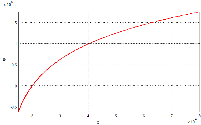
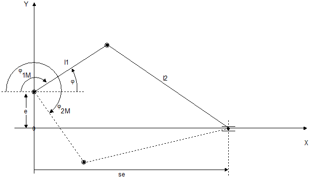
ID2: Crank

Example:
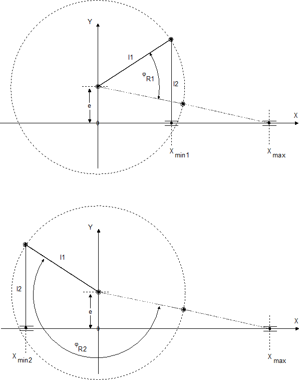
 | In the event of eccentricity e != 0 and specific parameter settings (e.g. (l2-l1) < e), there may be limits to the motor angle movement range because of jamming in the kinematic structure. In this case, the motor angle movement range of both solutions is smaller than 360 degrees (see figure below). |
ID3: Eccenter
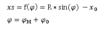
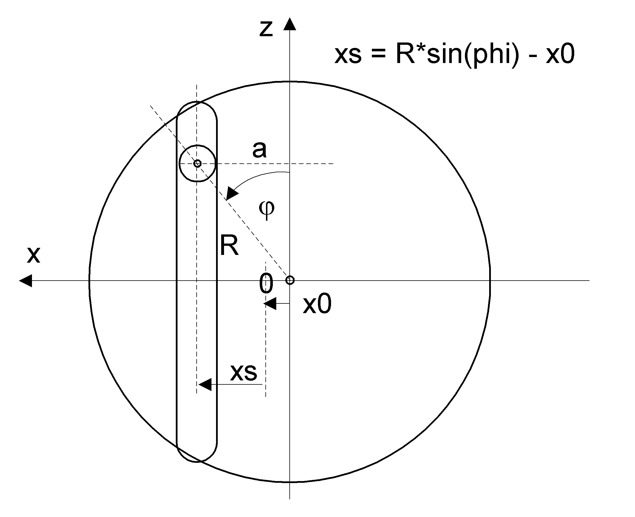
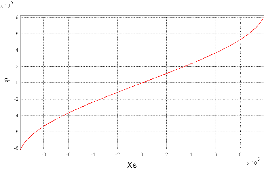
Example:
ID4: Crank with linkage by linear axis
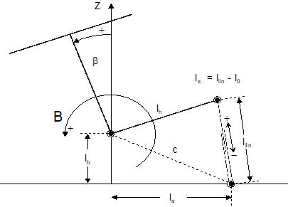
Example:
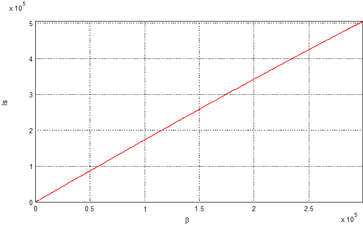
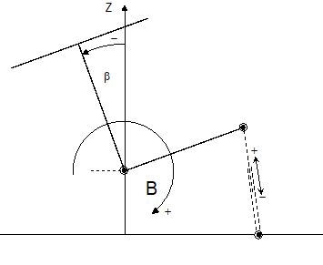
If the kinematic (β=0) is in zero position, the transformation delivers the drive position 0 for ls. If necessary, by param[3] an offset to this position can be defined. (Example: Drive position at β=0 is 50mm -> the offset value has to be set on 50mm). Mathematically, the default rotational direction of the B axis is positive. This can be adapted by the parameter trafo.command_pos.param[4], see figure below.
ID5: Angular kinematic
Available as of CNC Build V3.1.3107.41/V4.3.0.
A linear movement results from the angular movement.
The parameters specify the lengths l1,l2 and lh. The maximum excursions are defined by the parameters γmax and γmin.
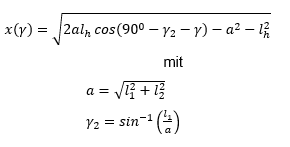
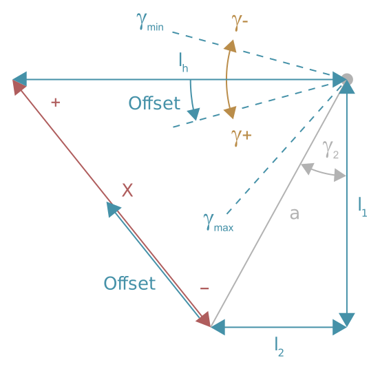
Example:
Below is the transfer function with and without position offset
Red: without position offset
Light blue: with posi8tion offset
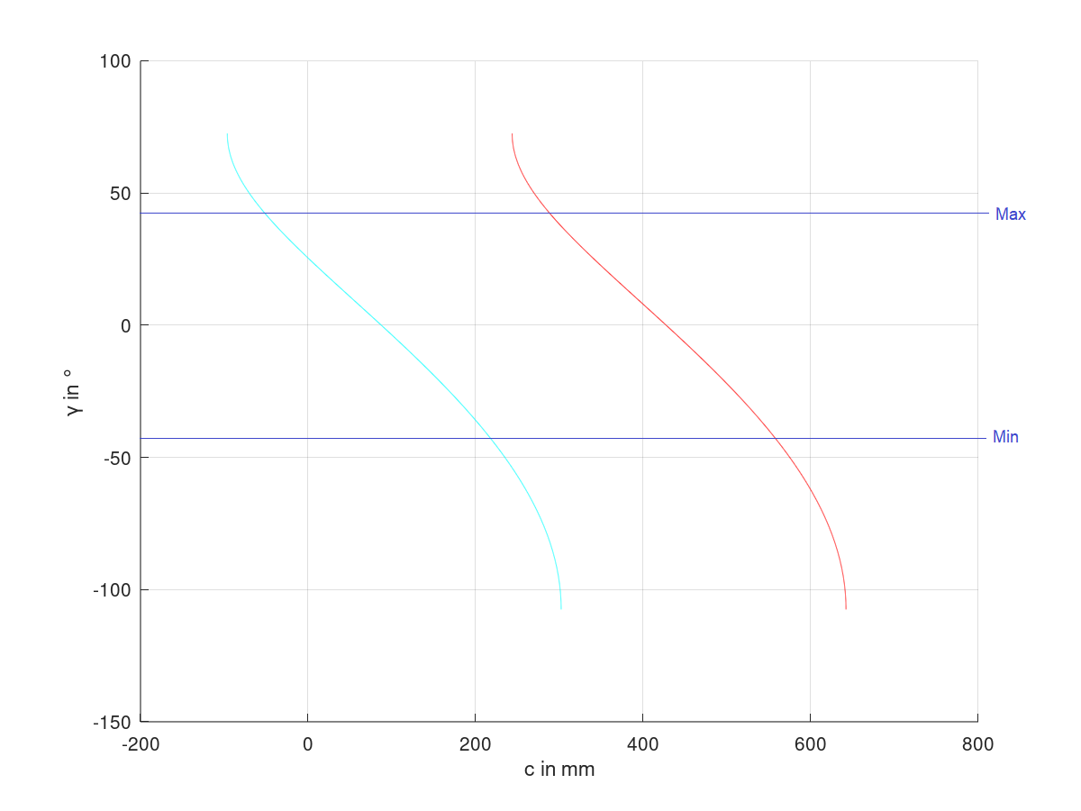
Angle offset and angle inversion
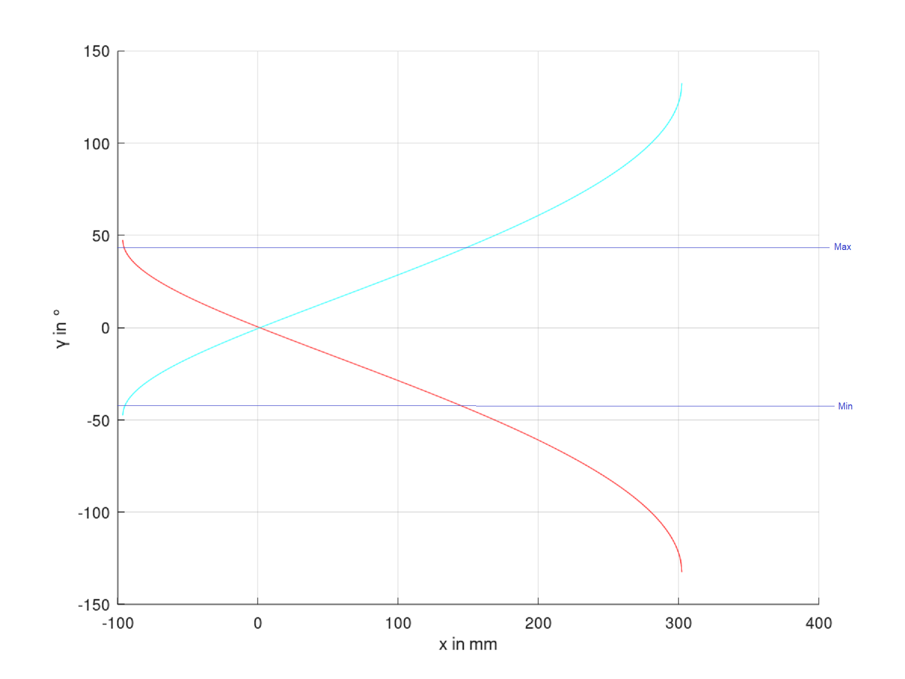
In addition to the example above, the angle can be provided with an angle offset by parameters and can also be inverted.
The following transfer function is with and without angle inversion.
Red: without angle inversion
Light blue: with angle inversion
Linear position inversion
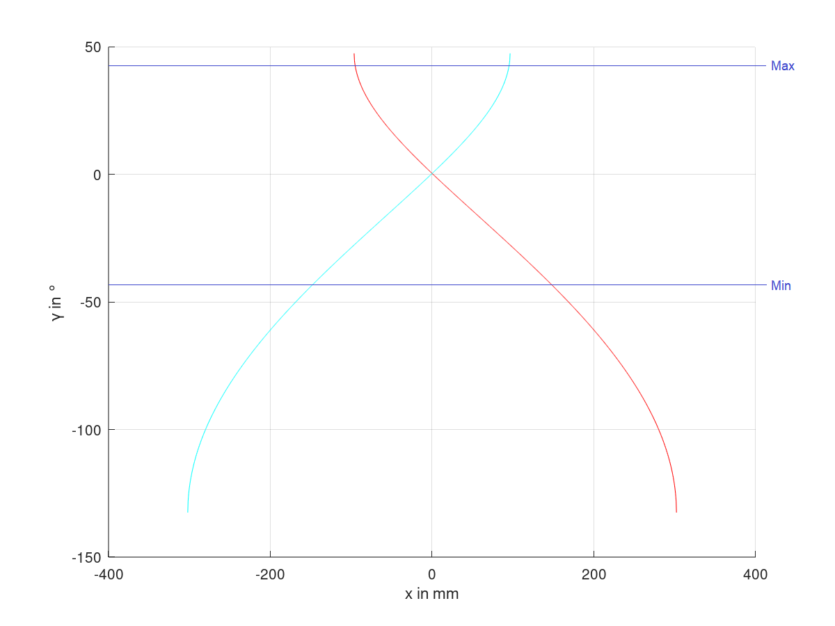
Based on the example above, the linear position can be inverted.
The following transfer function is with and without linear position inversion.
Red: without linear position inversion
Light blue: with linear position inversion
As a general rule, the following applies:
The specified angle of the kinematic has mathematical limits due to the specified input variables. If they are not observed, error ID 70342 is output.
ID 6: Symmetrical slider crank
In addition to identical lengths of crank and con-rod, this structure has an additional mechanical coupling between these elements so that no mechanical jamming can occur in the centre position of the slider (linear position).
Symmetrical slider crank solution range 0 to 180 degrees:
|
|
|
|
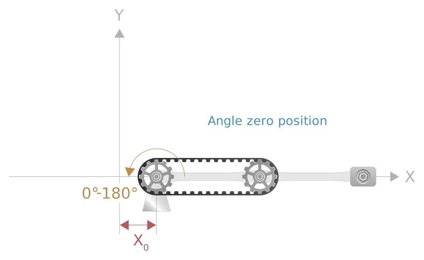
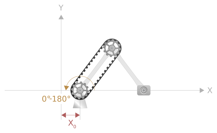
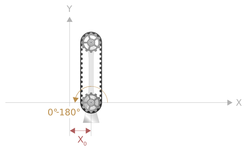
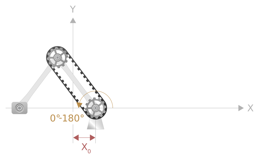
Symmetrical slider crank solution range 180 to 360 degrees:
|
|
|
|
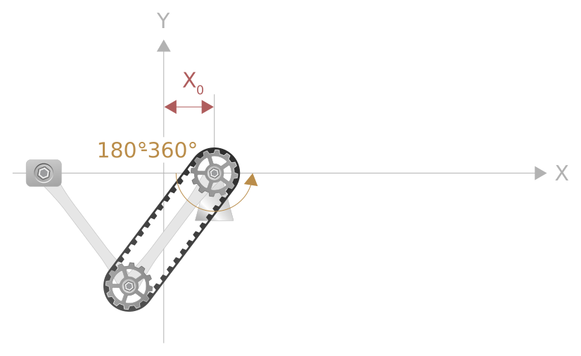
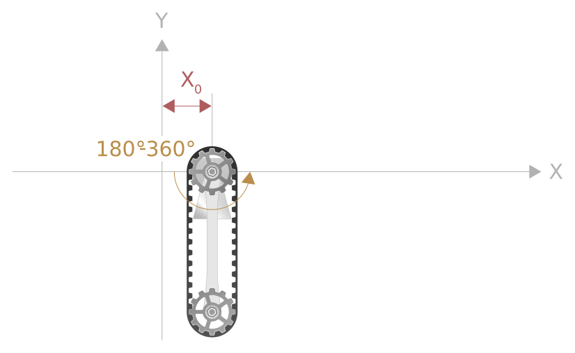
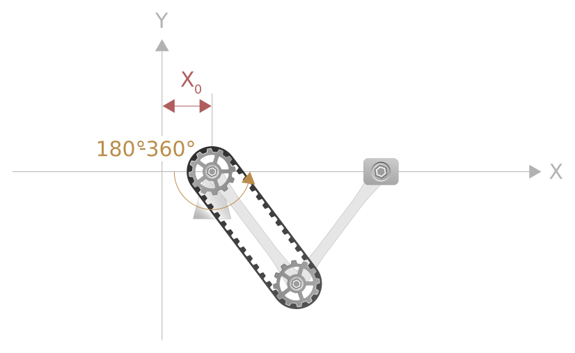
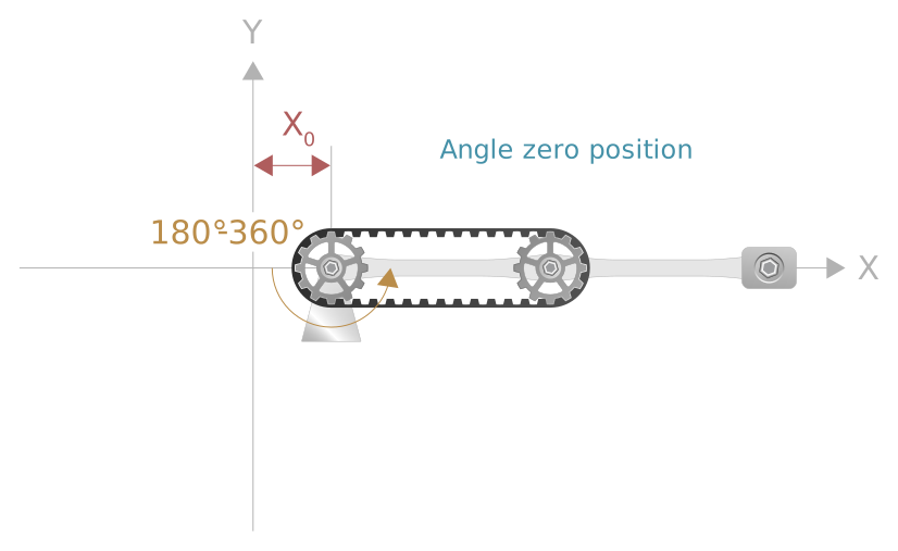
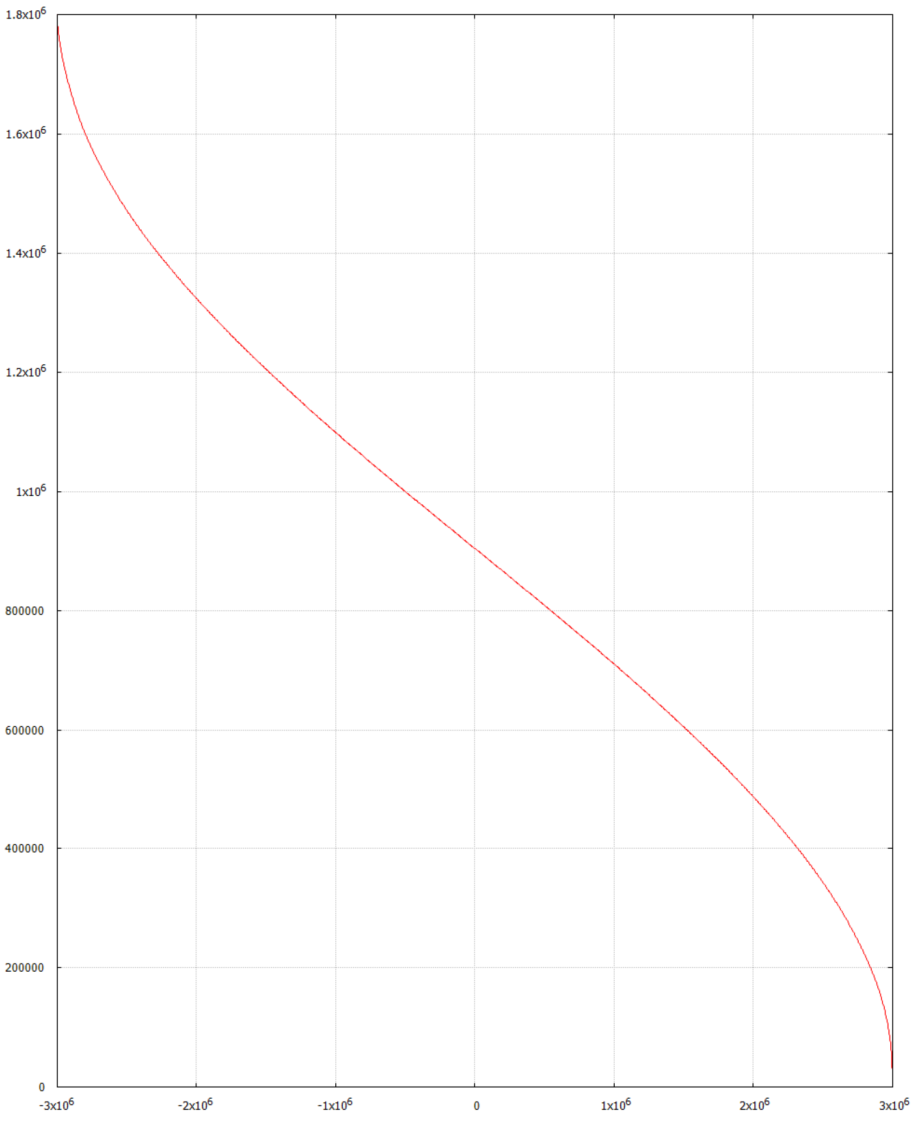
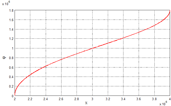
Example:
Transfer function φ= f(x)