Software filter
The EL3356 is equipped with a digital software filter which, depending on its settings, can adopt the characteristics of a Finite Impulse Response filter (FIR filter), or an Infinite Impulse Response filter (IIR filter). The filter is activated by default as 50Hz-FIR.
In the respective measuring mode the filter can be activated (0x8000:01, 0x8000:02) and parameterized (0x8000:11, 0x8000:12) (the EL3356-0000 supports only mode 0).
- FIR 50/60 Hz
The filter performs a notch filter function and determines the conversion time of the terminal. The higher the filter frequency, the faster the conversion time. A 50 Hz and a 60 Hz filter are available.
Notch filter means that the filter has zeros (notches) in the frequency response at the filter frequency and multiples thereof, i.e. it attenuates the amplitude at these frequencies. The FIR filter operates as a non-recursive filter. - PDO filter (valid as from firmware 05)
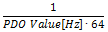
- The filter behaves like the 50/60 Hz FIR filter described above. However, the filter frequency can be adjusted here in 0.1 Hz steps by means of an output data object. The filter frequency range extends from 0.1 Hz to 200 Hz and can be reparametrized during operation.
- To do this the PDO 0x1601 (“RMB filter frequency”) must be displayed in the process data and the entry “PDO filter frequency” must be selected in the object 0x8000:11.
- This function allows the EL3356 to suppress interference of a known frequency in the measuring signal. A typical application, for example, is a silo that is filled and weighed by a driven screw conveyor. The rotary speed of the screw conveyor is known and can be adopted into the object as a frequency. Thus mechanical oscillations can be removed from the measuring signal.
- IIR-Filter 1 to 8
The filter with IIR characteristics is a discrete time, linear, time invariant filter that can be set to eight levels (level 1 = weak recursive filter, up to level 8 = strong recursive filter).
The IIR can be understood to be a moving average value calculation after a low-pass filter.
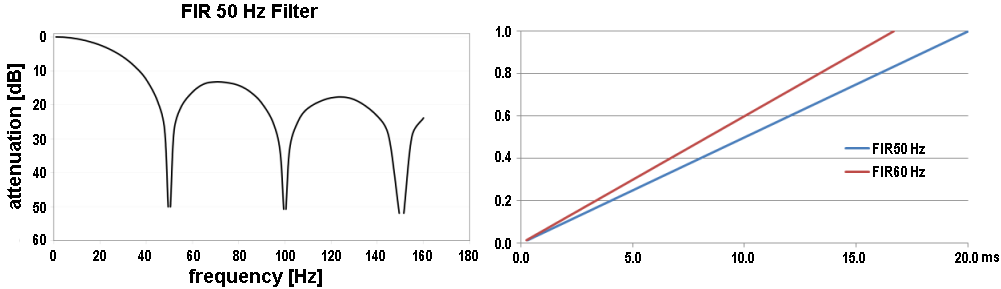
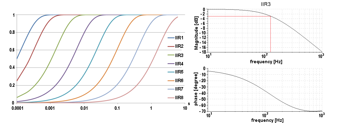
Overview of conversion times
Filter Settings | Value | PDO update time | Filter property | Limit frequency (-3 dB) [Hz] (typ.) | Comment | Rise time 10-90% [s] (typ.) | |
|---|---|---|---|---|---|---|---|
EL3356 | EL3356-0010 | ||||||
Filter deactivated | - | min. 10 ms | Cycle-synchronous, EL3356-0010 EL3356-0090 | - | - | - | - |
0 | FIR 50 Hz | min. 10 ms | 312.5 µs | 50 Hz notch filter | 22 Hz | Typ. conversion time 312.5 µs | 0.013 |
1 | FIR 60 Hz | min. 10 ms | 260.4 µs | 60 Hz notch filter | 25 Hz | Typ. conversion time 260.4 µs | 0.016 |
2 | IIR1 | Cycle-synchronous (up to min. 10 ms update | Cycle-synchronous (EL3356-0010: (EL3356-0090: | Low-pass | 2000 Hz | a0 = 1/21 = 0.5 | 0.0003 |
3 | IIR2 | Low-pass | 500 Hz | a0 = 1/22 = 0.25 | 0.0008 | ||
4 | IIR3 | Low-pass | 125 Hz | a0 = 1/24 = 62.5e-3 | 0.0035 | ||
5 | IIR4 | Low-pass | 30 Hz | a0 = 1/26 = 15.6e-3 | 0.014 | ||
6 | IIR5 | Low-pass | 8 Hz | a0 = 1/28 = 3.91e-3 | 0.056 | ||
7 | IIR6 | Low-pass | 2 Hz | a0 = 1/210 = 977e-6 | 0.225 | ||
8 | IIR7 | Low-pass | 0.5 Hz | a0 = 1/212 = 244e-6 | 0.9 | ||
9 | IIR8 | Low-pass | 0.1 Hz | a0 = 1/214 = 61.0e-6 | 3.6 | ||
10 | Dynamic IIR | The filter changes dynamically between the filters IIR1 to IIR8 | |||||
11 | PDO Filter frequency | min. 10 ms |
| Notch filter with adjustable frequency | approx. 0.443 * PDO value [Hz] | - | - |
 | Filter and cycle time If the FIR filters (50 Hz or 60 Hz) are switched on, the process data are updated maximally with the specified conversion time. (see table) The IIR filter works cycle-synchronously. Hence, a new measured value is available in each PLC cycle. |
| IIR filter Differential equation: Yn = Xn * a0 + Yn-1 * b1 |