| FM33xx-B110 - 12 and 32 channel analog thermocouple input plug (TC-Plug) |
Connection
Fieldbus/ supply voltage
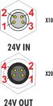
Connection supply voltage
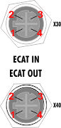
Connection fieldbus
Conn. point | Designation | Comment | |
|---|---|---|---|
X10 | 24 V IN | 1: Control voltage Us +24 VDC 2: Auxiliary voltage Up +24 VDC 3: GNDs 4: GNDp | Recommended Power cables |
X20 | 24 V OUT | ||
X30 | ECAT IN | 1: Tx + (Transmit Data +) 2: Tx - (Transmit Data -) 3: Rx + (Receive Data +) 4: Rx - (Receive Data -) | Recommended EtherCAT cables e.g.. ZK1090-6161-xxxx or ZK1090-6191-xxxx |
X40 | ECAT OUT | ||
- | PE | Screw connection - protective earth | |
Pin assignment for the 24-pin connection strip (FM3312-B110-0010)
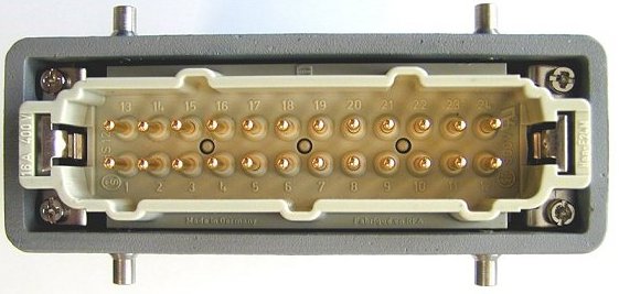
Connection strip FM3312-B110-0010
PIn | Meaning |
|---|---|
1 ...12 | TC1+ ... TC12+ |
13 ... 24 | TC1- ... TC12- |
Pin assignment for the 64-pin connection strip (FM3332-B110-1010)
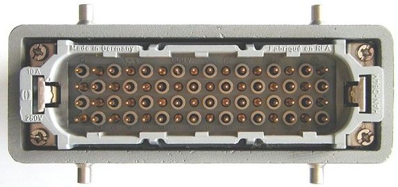
Connection strip FM3332-B110-1010
Pin | Meaning |
|---|---|
1 ... 16 (A..) | TC1+ ... TC16+ |
1 ... 16 (B..) | TC1- ... TC16- |
1 ... 16 (C..) | TC17+ ... TC32+ |
1 ... 16 (D..) | TC17- ... TC32- |
PE connection of earthed/floating thermocouples
The PE connection is responsible for the potential equalization of grounded and non-grounded thermocouples, and for thermocouples grounded at different potentials (see thermocouple measurement). The back voltage protection diverts mains voltages via the PE connection. This means that it is essential for proper earthing of the module to be guaranteed. When the module is being fitted, the PE connection should be established first. Connection of the module to the thermocouples via the connecting strip should be performed subsequently. In this way the risk of back voltage being present at the thermocouple inputs during assembly is avoided.
 WARNING