Basic function principles
Properties
The KL320x analog input terminals enable resistance sensors to be connected directly. The conversion and linearization of the resistance value into a temperature is done locally in the terminal. The measured values are output in the following scaling:
- for KL3201, KL3202, KL3204:
- Temperature measuring ranges: 1/10 °C (1 digit = 0.1 °C)
The elements PT100, NI100, PT200, PT500, NI120, NI1000 and PT1000 are implemented as resistance sensors over the specified measuring range. - Measuring range 10 to 5000 Ω: 1/2 Ω (1 digit = 0.5 Ω)
- Measuring range 10 to 1200 Ω: 1/16 Ω (1 digit = 0.0625 Ω)
(The internal resolution of the resistance value is 1/255 Ω) - for KL3204-0030 (temperature output only, NTC10K carel characteristic curve, resistance at 0 °C: 27280 Ω):
- Measuring range -40 °C to 110 °C: 1/10 °C (1 digit = 0.1 °C)
No resistance output possible!
In addition to this, a wire break or short circuit is reported to the bus coupler or to the controller, and indicated by the ERROR LED.
The terminal can be fully configured over the fieldbus. A self-defined scaling of the output can, for instance, be performed, or the temperature conversion can be switched off (not for KL3204-0030).
Process data output format
In the delivery state, the measured value is displayed in increments of 1/10° C in two's complement format (integer). The complete measuring range is output for each resistance sensor. Other display types can be selected via the feature register (e.g. sign/amount representation, Siemens output format).
|
Measured value |
Hexadecimal output |
Signed integer output |
|---|---|---|
|
-250.0°C |
0xF63C |
-2500 |
|
-200.0°C |
0xF830 |
-2000 |
|
-100.0°C |
0xFC18 |
-1000 |
|
-0.1°C |
0xFFFF |
-1 |
|
0.0°C |
0x0000 |
0 |
|
0.1°C |
0x0001 |
1 |
|
100.0°C |
0x03E8 |
1000 |
|
200.0°C |
0x07D0 |
2000 |
|
500.0°C |
0x1388 |
5000 |
|
850.0°C |
0x2134 |
8500 |
Resistance limit values
- R > 400 Ω: Bits 1 and 6 (over range and error bits) in the status byte are set.
The linearization of the characteristic curve is continued with the coefficients of the upper range limit up to the limit stop of the A/D converter (approx. 500 Ω for PT100).
- R<18 Ω: Bits 0 and 6 (under range and error bits) in the status byte are set.
The smallest negative number is displayed (0x8001 corresponds to -32767).
For over range or under range the red error LED is switched on.
Process data
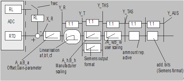
The process data that are transferred to the terminal bus are calculated using the following equations:
|
Variable |
Meaning |
|---|---|
|
X_RL |
ADC value of the supply cables |
|
X_RTD |
ADC value of the temperature sensor, including one supply cable |
|
X_R |
ADC value of the temperature sensor |
|
A_a, B_a |
Manufacturer gain and offset calibration (R17, R18) |
|
A_h, B_h |
Manufacturer scaling |
|
A_w, B_w: |
User scaling |
|
Y_R |
Temperature sensor resistance value |
|
Y_T |
measured temperature in 1/16 °C |
|
Y_THS |
Temperature after manufacturer scaling (1/10 °C) |
|
Y_TAS |
Temperature after user scaling |
|
Y_AUS |
Process data to PLC |
a) Calculation of the resistance value:
X_R = X_RTD-X_RL (1.0)
Y_R = A_a * (X_R - B_a) (1.1)
b) Curve linearization:
Y_T = a1 * Y_R2 + b1* Y_R + c1 (1.2)
or
Y_T = Y_R if output in Ω (1.3)
c) Neither user nor manufacturer scaling are active:
Y_AUS = Y_T (1.4)
d) Manufacturer scaling active (factory setting):
Y_THS = A_h * Y_T + B_h (1.5)
Y_AUS = Y_THS
e) User scaling active:
Y_TAS = A_w * Y_T + B_w (1.6)
Y_AUS = Y_TAS
f) Manufacturer and user scaling active: (1.7)
Y_1 = A_h * Y_T + B_h
Y_2 = A_w * Y_1 + B_w
Y_AUS = Y_2