Commissioning
| |
Open transformer circuits lead to electric shock and arc flashover! Disregarding this will result in death, physical injury or considerable damage to property!
|

| |
Hazardous voltage can lead to electric shock and burns!
|
| |
Induction of high voltages into the secondary circuit!
|
- Make sure that the working environment is safe during assembly, maintenance and installation work. Interrupt the power supply of the primary conductor and secure against being switched on again inadvertently.
- To connect the primary conductor, pull the engaged red connection cover plates upwards by the serrated surface.
Then feed the primary conductor (primary connection cross-section: max. 4 mm² with ferrule, 6 mm² solid, max. 8 mm² with cable lug) through the connection aperture of the current transformer housing. The connection apertures of the primary conductor are marked with the capital letters "K" and "L". - Connect the primary side conductor to the screw terminals "K" (input) and "L" (output) as shown in Fig. SCT0xxx connections.
- Now lead the secondary conductor through the connection aperture of the current transformer housing. The connection apertures of the secondary conductor are marked with the small letters "k" and "l".
- The secondary conductor must be connected to the screw terminals "k" (input) and "l" (output).
- After connecting the primary and secondary conductors, engage the red connection cover plates again with an audible “click”.
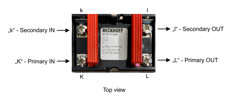 Fig.19: SCT0xxx connections
Measuring circuit
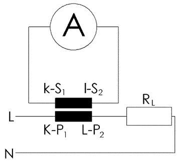 Fig.20: Measuring circuit - SCT0xxx/SCT1xxx/SCT2xxx transformer
Assembly notes
- Use the fastening plates provided to fasten the device to a mounting plate. These can be fastened to the mounting plate with two screws, max. Ø 5 mm.
- Fastening to a 35 mm DIN rail takes place with the help of the optionally available snap-on mounting ZB8201-0010.
- Check whether the current transformer is mounted correctly and the secondary conductors are connected correctly.
- Switch on the power supply to the primary conductor again.
- Optionally, the connections can be secured with the sealing plate ZB8202-0010, which is available as an accessory.
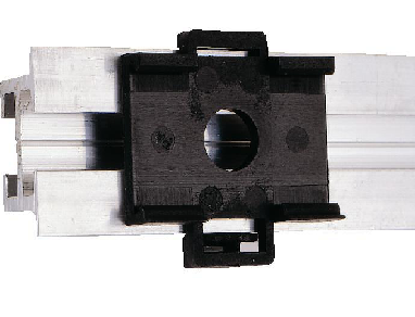 Fig.21: Snap-on mounting for 35 mm DIN rail, ZB8201-0010
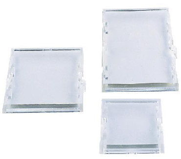 Fig.22: Sealing plate, ZB8202-0010