Further considerations...
The following section contains some practical notes from everyday use of analog measurement technology:
- Temperature plays a significant role in the verification of analog measurements with higher accuracy. In particular, many (all?) electronic processes are more or less temperature-dependent. On the device side, considerable effort is sometimes made to reduce this temperature dependency.
Nevertheless, both sources (power supply units, sensors) and measuring devices (EtherCAT Terminal, reference devices) should have stabilized thermally before use (see corresponding documentation); time ranges of >30 minutes are often required here.
Temperature changes can have a falsifying influence on the logged data, especially in the case of long-term measurements >1 h.
Examples of (hidden) temperature influence would be: - initial device heating after switching on,
- drafts, heat radiation from nearby devices/people, radiation effects e.g. from the sun (also in the non-visible range!),
- variable operation of the air conditioning
- Change of the installation position/adjacent terminals.
- Change of internal load (current flow, voltage level)
- Hand-held connections (plugs)
- This temperature dependence particularly applies to the load/source/sensor to be measured, e.g. an SG full bridge connected for testing. If, for example, a full bridge is modeled based on simple resistances, the resulting temperature coefficient is significantly higher than that of the measuring device (Beckhoff Terminal/Box). However, the voltage of a simple battery cell also shows a considerable temperature dependence!
- Current inputs can have a current-dependent internal resistance. Therefore, a control based on a voltage-controlled signal (e.g. power supply unit) may have misleading results
- Influences on the signal lines from electrodynamic/magnetic radiation must be taken into account; suitable shielding/grounding/protection components must be provided. The smaller (the amplitude of) the transmitted signals, the more important this becomes: analog level in the < 10 V range and mV and µV (thermocouples, measuring bridges/strain gages), and mA/µA in particular must be protected with effective shielding, if applicable with twisted pair cabling, or by routing cables at a distance from high-voltage/high-current cables.
Refer to the chapter Notes regarding analog equipment - shielding and earth in this documentation for more information on this. - When testing the behavior under changing signal amplitudes, the behavior of the source under changing load (= load shedding, load switching, level adjustment) also has to be considered.
Attention: the load of the sensor may change even if self test routines are running in the measuring device (terminal, box). - When using calibrators (= devices that output a target voltage/current/... according to the display) for testing/laboratory purposes, it is highly recommended that they are also measured with high-quality measuring devices (multimeters). If it is not explicitly ensured that the specific combination of calibrator (source) <-> Beckhoff analog input (sink: terminal, box) is harmonized, the display value of the calibrator is not to be trusted! The EMC protection circuits in the Beckhoff products required for industrial use can lead to oscillations and pumping effects that change the "true" signal on the line and bring it into conflict with the calibrator display value if the latter does not have its own back measurement function. An analytical look with the oscilloscope or the use of different calibrators can provide clarity.
- In general, it is advisable to consider the vendor data regarding the load/source/sensor, e.g. with regard to the last adjustment, thermal behavior, etc..
- For example, the information about the inherent noise of the source must be observed if the specified noise of the Beckhoff devices is to be checked with it. However, such noise data can only be found in high-order sources.
- The difference between calibration and adjustment/compensation is to be observed. A recent calibration (= assessment of the remaining deviation from a trusted normal) in itself is only meaningful, if the measurement took place within the tolerance assured by the vendor or was set accordingly based on an adjustment/compensation. The residual error after the adjustment, which is stated on the calibration certificate, may have to be taken into account manually.
- Many electrical measurements from sensor and measuring device are subject to an initial electrical offset, which can have a significant effect on the measurement. Examples include zero load of weighing scales (solution: tare) or open-circuit voltage in cables during voltage measurements. Especially (but not exclusively) for strain gauge measurements, it is helpful to carry out an offset correction immediately before the actual measurement, as this considerably reduces the offset component of the measuring channel of the terminal itself (see chapter Specification).
- If the terminal was exposed to condensation after transport/storage, it should be stored in a de-energized state until it is completely dry.
- Optional ventilation openings are to be kept generously free for free convection. See clearance recommendations in chapter "Mounting and wiring".
- For high-precision measurements, interference may also occur through thermovoltages in the mV/µV range. Specifically, this may occur if ferrules on stranded copper wire are used at the terminal point contact, due to a local shift of the point of different material pairing. In such cases it may be worth trying to plug the stranded wire directly into the terminal contact or to clean the contact.
- For measurements with currents > 100 µA, e.g. 20 mA current loop, loose connections such as hand-held measuring tips are not permitted under any circumstances! They lead to strong and fast fluctuating transition resistances which usually cannot be compensated quickly enough by the power source. Any connections must be clamped/screwed/soldered to ensure a reliable contact.
By the way: hand-held test probes can heat up as a result and lead to variable thermovoltage
- Two aspects are particularly relevant when using signal generators as signal transducers, especially during initial measurement trials with analog terminals or during filter trials:
- The amplitude of the output signal often drops suddenly with increasing frequency. For example, if 1 Vpp is set as the target amplitude, this is usually achieved cleanly for "slow" signals (less than 100 Hz, depending on the device), but not at frequencies greater than 100 Hz. This is then interpreted as an apparent measuring error of the analog input, since the analog input measures the real level. It is strongly recommended not to trust the graphical display of the signal generator but to measure the output signal with a third device, ideally a proven oscilloscope. It may be necessary to manually increase the amplitude at the signal generator, depending on the frequency, until the device reaches its control limit.
- Signal generators with graphic display (screen) are easy to set up, but only provide a target output signal that may not necessarily correspond to the actual measurable signal. The impedance setting of the output and the ground reference can be partly responsible for this.
Example: a Tektronix AFG3022B signal generator is connected on channel 1 in two-pole/differential mode to an ELM3004 in ±10 V mode and a signal with 1 Vpp, 1 Hz is set.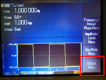
However, the terminal actually sees 2 Vpp, represented below by an associated TwinCAT Scope output: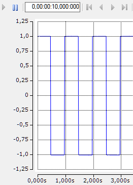
The reason for the "wrong" display of the signal generator is its output setting of "50 Ω" or "Load", i.e. it assumes a power-based level adjustment and thus also 50 Ω on the input side.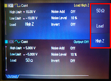
However, industrial analog terminals usually have input resistances of several 100 kΩ to MΩ. Therefore the impedance setting "HighZ" is the correct one in this case: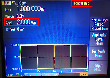
Electrically, the output signal has not changed during the changeover! Only the display on the screen changes.
Again, it is recommended to measure the output signal with a third device, a multimeter or oscilloscope, before starting the test. No dynamic signal [kHz] is required for this test, a DC or slow AC signal is sufficient.
- A few basic thoughts on resolution vs accuracy/measurement uncertainty:
High resolution (e.g. 24-bit) is stipulated in many cases for analog measurements, when it is in fact low measurement uncertainty = high measuring accuracy (e.g. ±0.005 % of the full scale value) that is required. The implicit assumption is that measurements with high resolution will automatically provide low measurement uncertainty. However, both properties are initially independent of each other.
The resolution quantifies the interval size that leads to a digital distinguishability in the measurement result, e.g. a change of 20 mV in the analog signal is only detected if the resolution is also smaller than 20 mV, the resolution being technically determined by the reference voltage and the number of bits. However, this is still independent of the extent to which the resolvable value corresponds to the true value.
Basically, the following applies: resolution results from the circuit design, low measurement uncertainty/high accuracy (above all) from the adjustment - wherein both fields are demanding.
There are various influencing factors that worsen the measuring accuracy:
If an influencing factor is known and describable, it is to be assigned to the systematic measurement uncertainty. For example, a temperature or characteristic curve influence can be quantified and then usually compensated for in the production adjustment or at operating time; the resulting effort can be reduced here by clever design.
The other major influence on the effective measuring accuracy is due to random influencing variables: the inherent noise of the electronics, as well as others in the entire measurement chain. These measurement uncertainties are characterized by the fact that they cannot be described deterministically and the deviation of the measurement results from measurement to measurement is of a purely random nature. Here, the user has a large scope of action, because by averaging over several measurements, the measuring accuracy of the calculated result can be increased. Because truly random fluctuations are considered to have no mean values, their effect on the measured value can be reduced by mean value filtering. The disadvantage of this is a later completion time of the measurement: "the result is available".
The one extreme is to process unchanged "raw data", i.e. the individual noisy measured values in the control cycle without delay, i.e. individually. The other extreme is to average or smooth over (almost infinitely) many measured values - this leads to a corresponding time delay, which is very unfavorable for a control loop. However, this effectively eliminates the random influence on the measurement result and the output value approaches the true (practically indeterminable) value more and more - under the above-mentioned assumption, of course, that the noise is equally distributed and thus the "Filter" tool may also be applied to the data for this purpose or does not distort the result.
Between these two extremes lies the range in which the user now has to select the filters in the application in view of the max. permitted delay and the required smoothing.
In general, it can be assumed that the faster a channel samples, i.e. the higher the usable data rate, the higher its inherent electrical noise will be. It is not for nothing that high-precision measuring devices operate with sample rates in the range of 1/min or slower.
Two examples for a measuring range of ±10 V and comparable sampling rate:
Note: 24 bits/bit positions result in a value space of 224 = 16,777,216 digits. Since the first bit is usually used as a sign, 223 = 8,388,608 digits remain as the available unipolar number range.
Example 1: 24-bit resolution incl. sign over measuring range ±10V → 1.19 µV/digit
Assumption: inherent noise of the measuring electronics of 10 bits (the lower 10 bits) and thus "many wiggling bits, i.e. few standing bits"
Result: a measurement inaccuracy to be expected from this alone (without averaging) of 210 digits * 1.19 µV/digit = 1.2 mV
Example 2: 16-bit resolution incl. sign over measuring range ±10 V → 305 µV/digit (i.e. 256x worse resolution)
Assumption: inherent noise of the measurement electronics of 1 bit (15 standing bits)
. Result: a measurement inaccuracy to be expected from this alone (without averaging) of 0.6 mV
Note: of course, a lot of other factors like resolution step, temperature, etc. contribute to the total measuring error, but in this section the focus is on the noise of the electronics.
So in this not unrealistic example, the 16-bit channel would effectively be more accurate than the 24-bit channel.
By averaging (statistics) over a (high) number of samples, the effective measurement uncertainty of both example channels could now be lowered. This is only dependent on the time available. The longer the averaging period, the more "standing bits" can be determined from the noisy data stream: in the above 16-bit example, the 15 standing bits can account for 16 or even more (17 or 18) bits, e.g. by activating the terminal's internal mean value filter – provided the user is prepared to accept a slower update rate or a long signal delay, corresponding to a low-pass filter. This calculation could take place locally in the measuring device (and in fact reduce the output rate) or it must take place in the central PLC.
Conclusion: a high digital resolution is not the sole cause of good measurement quality, but it is useful as a basis for subsequent sophisticated data manipulation with the aim of achieving the truest possible measured value as quickly as possible.
- The source impedance in relation to the measuring device impedance is of great importance for correct measurement! Increased source impedance (high output resistance) means that the source can only drive a small amount of current. This has implications in three areas:
- In general, the effect of the unavoidable voltage divider RSource/RMeasuring device can be observed: the measurable signal amplitude sometimes changes considerably if overall “slow” changes occur at one point in the system (measuring source - measuring device): e.g. the device of one side is exchanged or the resistances change due to temperature (self-heating, daylight, ...).
- Signals in the LF/HF range are affected by unavoidable capacitive/inductive cable loads: if necessary, an intended voltage amplitude is not achieved because the source “does not provide sufficient power” due to the high source impedance and the “low-pass effect” of the cable load on an alternating quantity becomes apparent in such a way that “too little time is available to build up the signal”.
- Furthermore, “fast” changes to the system can eventually lead to irritation of the low-power source and to resonances (see also Note on oscillation effects with analog 20 mA inputs).
- The previously mentioned effects can lead to a problem area when measuring small signal voltages, which would have to be considered for low-power sources such as thermocouples.
Example: IR sensors (respond to temperature radiation, comparatively like thermocouples) are usually high impedance (some 10 kΩ) and low power. In connection with a multiplex input circuit (keyword: “fast” system change) and a standard thermocouple terminal, there may be a reaction on the connecting line, a measurement close to the application is hardly possible: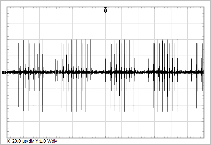 A simultaneous acquisition (e.g. EL3314-0002) or very high-impedance measuring devices (e.g. ELM3344) provide a remedy.